
The ROOST booster would expend a total of 8,574,000 pounds (3,889,000 kilograms) of propellants during its 292-second (nearly five-minute) climb to orbit. As the countdown reached zero, the 12 engines would ignite simultaneously. There would follow a brief hold-down period during which engine performance would be checked. If any of the main engines did not function as expected during checkout, all would be turned off. If all 12 engines functioned as planned, however, the hold-down fixtures would be released and the ROOST booster would thunder off the pad.
After a vertical climb lasting 14 seconds, the ROOST booster would gimbal (pivot) its engines by up to 6° to pitch eastward toward the sea. It would encounter maximum dynamic pressure at an altitude of 40,500 feet. Acceleration would increase as the single-stage vehicle expended its propellants, reaching six times Earth’s surface gravity (6 Gs) 216 seconds after liftoff. Half of the main engines would then shut down to maintain acceleration within tolerable limits for any astronauts atop the booster.
During crew launches a launch escape tower akin to the one atop the Mercury capsule would stand by until after orbit injection to pull the ROOST crew capsule free in the event of ROOST booster malfunction. The presence of astronauts would shape the normal ROOST booster ascent trajectory; launch escape followed by ballistic reentry and ocean splashdown would remain possible until late in the climb to orbit. Bono and his colleagues emphasized their reusable booster, however, so provided little information on the design of the escape system, crew spacecraft, or, indeed, any ROOST payload/crew system.
Six main engines would continue to operate for a further 76 seconds, during which acceleration would top out at 6.7 Gs. Shutdown would occur at 256,000 feet (78,029 meters) with the ROOST booster traveling at 26,300 feet per second (8016 meters per second), a velocity sufficient to enable it to coast to apogee at its 300-nautical-mile (555.6-kilometer) operational altitude in about 30 minutes. During coast the launch escape tower would separate from the crew spacecraft (if one were carried).
At main engine shutdown the ROOST booster and payload would have a mass of 1,026,000 pounds (465,486 kilograms). The main engines would not operate again until the next time the ROOST booster lifted off from its seaside base.
Bono and his co-authors believed that the main engines were a key factor in the ROOST booster’s bid for economical reusability. They cited the opinion of an unnamed rocket engine manufacturer when they stated that replacing the nickel steel cooling tubes typical in rocket engine bells with stainless steel cooling tubes would by itself stretch ROOST booster main engine life to 4000 seconds. They cited the main engine burn times — six would operate for 216 seconds per flight and six for 292 seconds — when they estimated that each main engine could perform between 13 and 18 flights before a major overhaul would become necessary. A major overhaul would cost between 40% and 50% of the original cost of the engine.
The ROOST booster would include four secondary engine “quads” near the broad bottom end of the tapered transition section. Bono and his co-authors called these “cruciform engines.” During ascent they would be shielded from aerodynamic heating by ejectable covers.
As the terms “quad” and “cruciform” imply, the four 10,000-pound-thrust (4536-kilogram-thrust) engines making up each quad would be arranged to resemble a “+” sign. The engines would burn storable hypergolic (ignite-on-contact) hydrazine fuel and nitrogen tetroxide oxidizer drawn from eight pressurized tanks in the transition section. Half of the 16 secondary engines could fail without degrading performance during the seven sequential maneuvers they would need to carry out during each ROOST flight.
The secondary engines would first be used to provide attitude control during coast to apogee, then the four aft-facing secondary engines would ignite at apogee and burn for eight minutes to circularize the ROOST booster’s orbit. At the end of the circularization burn the ROOST booster and payload would weigh 956,000 pounds (433,634 kilograms).
 |
| Key to ROOST booster launch painting. A = crew vehicle with launch escape tower; B = tapering transition section with secondary propulsion system quads under aerodynamic shields; C = flaring base section with cylindrical housing for main engines and upper part of drag cone; D = transport barge/launch pad with servicing gantry; E = launch basin; F = rocket engine exhaust vent (1 of 2); G = swinging canal lock doors for sealing off launch basin (2); H = water-filled canal leading to launch basin; I = pumping station for removing water from launch basin when canal lock doors are closed; J = pumping station for liquid oxygen; K = barge carrying super-insulated tank containing liquid oxygen; L = high-pressure gas (helium and oxygen) tanks with adjacent railroad tank cars; M = receiving dock. Image credit: Douglas Aircraft Company/DSFPortree via San Diego Air & Space Museum. |
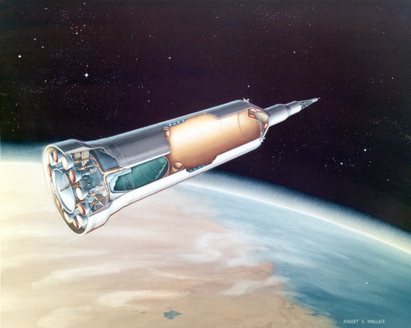 |
| Cutaway of ROOST booster in Earth orbit prior to payload separation. See next image for explanation. Image credit: Robert S. Wallace/Douglas Aircraft Company via San Diego Air & Space Museum. |
 |
| Key to cutaway painting of ROOST booster in Earth orbit prior to payload separation. A = crew vehicle with launch escape tower; B = secondary propulsion system engine quad (one of four); C = interior of tapering transition section with pressurized hypergolic propellant tanks and dome-shaped top of LH2 propellant tank; D = LH2 propellant tank; E = cluster of four helium tanks (one of two) within LH2 propellant tank; F = torus-shaped “recovery bag” LH2 tank within main LH2 tank; G = main LOX propellant tank; H = base section with cylindrical housing for main engines and upper part of drag cone; I = main engine (one of 12); J = canister containing lower part of drag cone. Image credit: Robert S. Wallace/Douglas Aircraft Company/DSFPortree via San Diego Air & Space Museum. |
The four forward-facing secondary engines would then ignite to brake the booster slightly to facilitate separation of the 360,000-pound (163,290-kilogram) payload and to settle 62,000 pounds (28,123 kilograms) of trapped LOX in the main propulsion system so that it could be vented overboard. The ROOST booster would then be permitted to tumble in orbit until time came to collect a free-flying 30,000-pound (13,608-kilogram) payload for return to Earth.
The Earth-return payload might take the form of a 12-man capsule with an emergency escape system. The secondary engines would stabilize the ROOST booster to permit the capsule to safely link up with the transition section, replacing the payload delivered to orbit.
From the beginning of its orbital tumble until after rendezvous and docking with the Earth-return payload, the ROOST booster would gradually deploy and inflate its 107,000-pound (48,534-kilogram) reentry and recovery system. This would take the form of a two-part “inflatable blunt body drag cone” measuring 226 feet (68.9 meters) tall by 325 feet across when fully inflated.
The upper part of the drag cone would be made of relative fragile materials — dacron sheets bonded together with silicone sealant. A pair of load-bearing membranes would support the ROOST booster’s weight during reentry, while a torus-shaped structure with an inflated volume of eight million cubic feet (226,535 cubic meters) surrounding the middle portion of the ROOST booster would enable the drag cone to maintain its overall shape.
Bono and his co-authors noted that the quantity of gas in the torus would be roughly equivalent to that in the twin helium-filled Akron-class dirigible airships operated as flying aircraft carriers by the U.S. Navy in the 1930s. The Akron and the Macon each measured about 785 feet (239 meters) long. The comparison was perhaps unfortunate because neither airship lasted long — the Akron, launched in 1931, crashed with the loss of most of its crew in 1933 off the coast of New Jersey, and the Macon, completed in 1931 and first flown in 1933, was damaged in a storm and lost off the California coast in 1935.
The lower part of the drag cone, which would become its forward-facing “nose” during reentry (and thus would be exposed to the greatest aerodynamic heating) would comprise Rene 41 or stainless steel wire cloth coated with silicone sealant. It would be made up of “airmat” cells, so would tend to hold its shape even when not filled with gas.
Two arcuate sections of the lower skirt surrounding the main engines would detach, exposing the carefully packed upper part of the drag cone. Thermal radiation from the Sun and Earth would heat LH2 left over in the LH2 propellant tank after main engine operation, causing it to turn to gas. In a normal booster, if responsible practices were observed, gaseous hydrogen would be vented overboard to prevent the tank from overpressurizing and bursting explosively, but in the reusable ROOST booster the gas would be piped into the upper part of the drag cone to slowly inflate it ahead of reentry. Gradual inflation would, the Douglas engineers explained, help to prevent the upper drag cone from overinflating and bursting.
The lower part of the drag cone, meanwhile, would deploy from a cylindrical canister surrounded by the 12 main engines. Helium gas drawn from eight spherical “bottles” mounted within the LH2 propellant tank would be used to inflate the lower drag cone.
 |
| ROOST booster in Earth orbit at start of inflatable drag cone deployment. The lower and upper parts of the drag cone can be discerned (the upper part is torus-shaped and orange; the lower part, to the left of the upper part, appears silvery). Visible at left are the two arcuate sections of the cylindrical lower skirt which housed the main engines and, surrounding them, the stowed upper part of the inflatable drag cone. Also visible at left is the disc-shaped cover of the cylindrical canister that held the stowed lower part of the drag cone. At center right eight red hypergolic propellant tanks can be seen within the tapering transition section through the opening left by separation of the payload the ROOST booster delivered to orbit. Image credit: Douglas Aircraft Company via San Diego Air & Space Museum. |
 |
| Cutaway painting of ROOST booster with Earth-return payload and fully deployed inflatable drag cone at start of reentry. See next illustration for explanation. Image credit: Robert S. Wallace/Douglas Aircraft Company via San Diego Air & Space Museum. |
 |
| Key to cutaway painting of ROOST booster with Earth-return payload and fully deployed inflatable drag cone at start of reentry. A = Earth-return payload; B = secondary propulsion system engine quad (one of four); C = tank section encapsulated by two-part drag cone; D = torus-shaped upper drag cone inflated section; E = lower drag cone showing airmat cells. Image credit: Robert S. Wallace/Douglas Aircraft Company/DSFPortree via San Diego Air & Space Museum. |
 |
| Cross section of ROOST booster with fully deployed drag cone and selected dimensions. A = Earth-return payload; B = secondary propulsion system engine quad (1 of 4); C = LH2 propellant tank; D = LOX propellant tank; E = base section. During reentry the center of gravity is located in the upper third of the LOX tank. Image credit: Douglas Aircraft Company/DSFPortree. |
Bono and his co-authors explained that the ROOST booster would overfly its seaside base about every 12 hours. They thus designed the booster for an orbital lifetime of 24 hours to provide two opportunities for acceptable weather conditions in the recovery area, a 46-nautical-mile-diameter (85.2-kilometer-diameter) circular ocean zone centered about 50 nautical miles (92.6 kilometers) from the ROOST base receiving dock. Among other factors determining orbital lifetime was the damage expected to be caused over time by micrometeoroid impacts.
Earth-return would begin with an “orbit rejection” maneuver, which would see the four forward-facing secondary engines burn for nearly four minutes to reduce the ROOST booster’s orbital velocity by 500 feet (152 meters) per second. During ROOST crew-return missions, astronauts on board would start and end the precise maneuver; during cargo missions, when no crew was on board, transmitted commands from a ground station would fill in.
The secondary engines would then perform attitude control maneuvers so that by the end of a 30-minute coast period, at the start of atmosphere reentry at an altitude of 400,000 feet (122,000 meters), the ROOST booster would be oriented at an entry angle of 1.5°. This angle would minimize aerodynamic heating of the drag cone while enabling control sufficient to ensure landing in the designated landing zone.
At an altitude of 235,000 feet (71,630 meters), 250 seconds after the start of reentry, the ROOST booster would experience deceleration of 3.4 Gs. By then the temperature experienced by the lower part of the drag cone would be decreasing from a peak of 1520° F (827° C). Maximum deceleration of 6.75 Gs would occur 300 seconds after the start of reentry at an altitude of 204,000 feet (91,200 meters), by which point the ROOST booster would have slowed to a speed of Mach 11.8.
Bono and his co-authors aimed to make the inflated drag cone aerostatically buoyant, like an airship, before it reached the surface of the ocean. To accomplish this, starting at an altitude of 100,000 feet (30,480 meters) LOX from a special small “heater tank” inside the booster’s LOX propellant tank and LH2 from a torus-shaped “recovery bag” tank inside the LH2 propellant tank would be fed into a combustion chamber and ignited, yielding hydrogen and steam. The hot combustion products would then be fed into the drag cone to raise its internal temperature, thus increasing its buoyancy.
At an altitude of 2000 feet (610 meters) above the ocean, with upper drag cone internal temperature at 400° F (204° C), the ROOST booster would slow to a stop and the heated gas flow would end. The gas in the upper drag cone would then cool and the ROOST booster would begin a descent to the ocean surface lasting about 16 minutes, with a final speed at “splash down” of just 2.5 feet (0.76 meters) per second. The relatively stiff lower part of the drag cone and slow landing speed would prevent salt water from contacting the ROOST booster’s solid structure (and, especially, its main engines), helping to ensure fast and cheap refurbishment ahead of its next flight.
During its slow final descent the ROOST booster would automatically deploy several sea anchors and tow cables. These would on contact with the water dissipate static charge built up during reentry and create drag, helping to prevent surface winds from pushing the floating booster away from the landing area. As it floated in the ocean swell the returned ROOST booster and payload would weigh 568,580 pounds (258,000 kilograms).
Meanwhile, a recovery force would move to intercept the returning ROOST booster. It would comprise a modified destroyer or destroyer escort ship with engines capable of generating 12,000 horsepower at its propeller shaft, a C-47 cargo airplane, and three H-21 helicopters. During night-time landings radar tracking and a radio beacon on the ROOST booster would guide the recovery force; during daylight landings, the helicopters would also patrol the landing zone and seek to spot the returning booster visually.
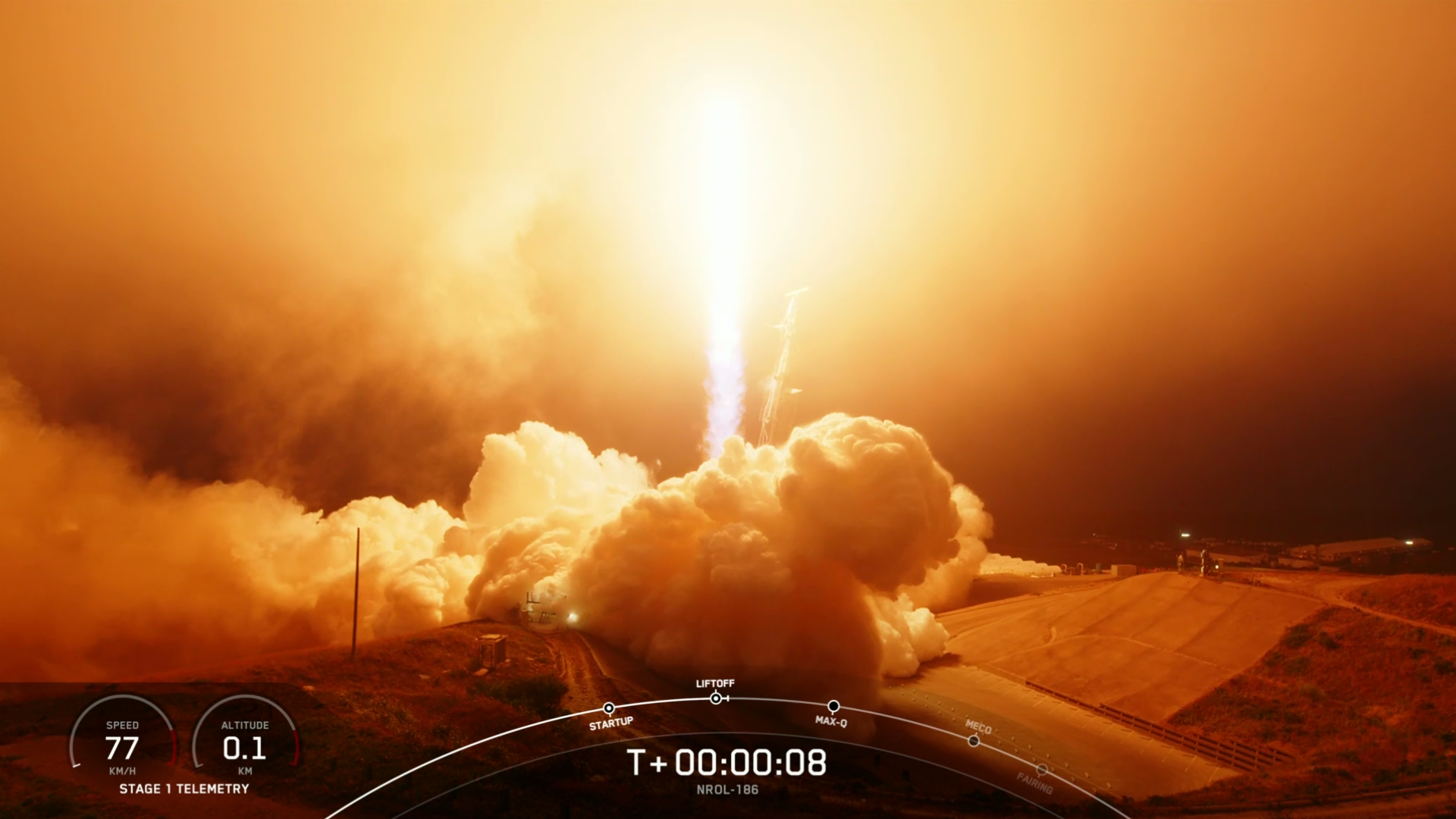
Sailors on the surface ship would take on board the tow cables and attach them to a powered winch. If astronauts were on board the ROOST booster, a helicopter would hover over the crew capsule and lower a retrieval basket to recover them for transfer to the surface ship. The sea anchors would then be collected and the surface ship would set out for the ROOST base receiving dock at a speed of 10 knots (assuming a 20-knot headwind) (see image at top of post). Depending on the touchdown point and the modest rate of surface drift expected, the tow-back distance might range between 27 and 73 nautical miles (50 and 135 kilometers).
Upon arrival at the receiving dock, the tow cables would be transferred to a winch on a waiting barge/launch pad. A hose on the barge/launch pad would then be used to pump hot steam and hydrogen gas from a combustion unit into the upper part of the drag cone to restored its buoyancy.
With the ROOST booster floating above the water, technicians would remove the lower part of the drag cone, attach a hose, and pump out the helium inside it for reuse. Removal of the lower drag cone would expose the booster’s flared base and 12 main engines.
The technicians would then attach the base of the hovering ROOST booster to the hold-down fixtures on the barge/launch pad, taking care to move slowly so as not to cause damage. After the booster was firmly bolted down, they would detach the upper part of the drag cone from the booster and allow it to rise above the payload at the top of the tapering transition section. Bono and his co-authors called this “‘skyhook’ buoyancy feature” a “fringe benefit” of their inflatable drag cone recovery system.
Once the upper part of the drag cone was free of the booster, technicians would pull it down onto the barge/launch pad and attach hoses to remove its hydrogen and flush it with nitrogen. The barge/launch pad would then transfer the ROOST booster and its recovery system components down the main canal to the assembly building for refurbishment ahead of their next launch.
Though Bono and his co-authors stated that the ROOST booster was too large to be moved except on water, near the end of their report they proposed that, after operational reliability was demonstrated, ROOST booster assembly, launch, landing, and refurbishment at a land (most likely desert) base might become possible. This would, they wrote, make ROOST especially attractive “after our coastal [launch and splashdown] ranges have eventually become saturated” with rocket traffic.
They suggested as a possible land site the wide-open spaces of Edwards Air Force Base, north of Los Angeles. Polar launches from Edwards would overfly communities located between Los Angeles and San Bernardino, while launches to near-equatorial orbits would overfly the central California community of Barstow.
Bono and his co-authors then provided details of the 14-year ROOST program schedule as part of their attempt to estimate system reliability and manufacturing, operations, and refurbishment costs. They explained that four years would be spent designing, developing, and testing the ROOST booster, with the first booster arriving at the seaside launch base midway through the third year. Following assembly and transfer to the launch complex, a static engine test would occur. The ROOST booster would be held down while its main engines fired for some period of time.
The first research and development orbital test flight would take place midway through the fourth year. Assuming a successful first test flight, the flown booster would be refurbished and launched on a second test flight before the end of the year. If the first test flight ended in loss of the ROOST booster, a second booster would attempt a test flight by the end of the fourth year. Operational flights would then begin early in the fifth year and continue for a decade.
The overarching goal of the 10-year operational ROOST program would be to deliver 64 million pounds (29.03 million kilograms) of cargo to low-Earth orbit. Booster reliability would be an important factor in determining the number of flights required to achieve this and thus the flight rate and number of ROOST boosters required. Bono and his co-authors assumed an 80% reliability rate in the operational program’s first year — that is, loss of one in five ROOST boosters launched — and a total of eight flights.
This was an ambitious target; at the time the Douglas engineers prepared their report, U.S. boosters typically suffered much worse failure rates. The missile-derived Atlas, for example, had flown 12 times with seven failures, for a success rate of only 41.8%. The Douglas engineers noted that Atlas was basically a two-stage launch vehicle, and that five of its failures had been attributed to its second stage. They contended that their single-stage booster would be immune from many possible failure types, including (to cite the most obvious example) failure of the second stage to ignite.
In the second year of the 10-year operational ROOST program, reliability would increase to 90%, where it would remain throughout the test of the program. Launch rate would climb to 12 flights per year. In its third year, the operational ROOST program would achieve its maximum launch rate of 24 flights per year. The ROOST program would need a total of 199 flights.
Taking into account these loss and launch rates and the total number of ROOST flights needed, Bono and his co-authors then calculated that the operational ROOST program would require a total of 27 ROOST boosters to achieve its 64-million-pound (29.03-million-kilogram) goal. Each booster would cost $39.1 million, for a total booster hardware cost of $1.056 billion. ROOST cost would total $2.989 billion over the course of the 14-year program.
The Douglas engineers then proposed “for comparison purposes” a hypothetical, conjectural expendable One-stage Orbital Space Truck (OOST) booster identical to the ROOST booster but without recovery systems. They assumed that recovery system weight saved could be applied to increase payload and that the OOST booster would be more reliable than the ROOST booster because it would not be subjected to the risks inherent in reentry, recovery, and refurbishment.
They found that a total of 139 OOST flights — and thus 139 single-use OOST boosters — would be required. Each OOST booster would cost just $20.8 million and the reduced number of flights would mean that only two launch complexes would be necessary to carry out the OOST program, not three.
A total of 139 expendable OOST boosters would, however, cost $2.895 billion — nearly three times as much as the 27 ROOST boosters. The savings generated by eliminating the third launch complex ($48 million) and all recovery and refurbishment operations ($64 million) would fall far short of justifying development of the OOST booster in place of the ROOST booster. Total OOST program cost over 14 years would reach $4.568 billion, or $1.673 billion more than the ROOST program.
Bono and his co-authors asserted that their cost estimates fell within 10% of actual costs. How they could be certain of this was, however, not made clear. Their study was almost certainly too preliminary to support cost estimates of that degree of precision.
While novel and apparently promising, the ROOST proposal gained little traction. In part this was because Bono and his co-authors appear not to have spent much time promoting it. Bono would within a year move on to another type of wingless, reusable, single-stage launch vehicle — one without any inflatable parts. His Reusable Orbital Module (Booster and Utility Shuttle) (ROMBUS) system included many of the characteristics of systems he would promote throughout the remainder of his career. ROMBUS will be discussed in a future post.
Phillip Bono remained with Douglas (known as McDonnell Douglas after its 1967 merger from McDonnell Aircraft Corporation) until his retirement in 1988. He died in 1993, shortly before the company carried out an (ultimately abortive) series of non-orbital tests using subscale prototype Delta Clipper reusable single-stage-to-orbit vehicles.
Sources
An Integrated Systems Study for a Reusable One-Stage Orbital Space Truck (ROOST), P. Bono, F. Bergonz, and J. Hayes, Douglas Report SM-42597, Douglas Aircraft Company, Inc., Missile & Space Systems Division, December 1962.
“ROMBUS — An Integrated Systems Concept for a Reusable Orbital Module (Booster and Utility Shuttle),” Paper No. 63-271, P. Bono; paper presented at the American Institute of Aeronautics and Astronautics Summer Meeting in Los Angeles, California, 17-20 June 1963.
“Philip Bono, Reusable Rocket Booster’s Designer, Dies at 72,” G. Hernandez, Los Angeles Times, 27 May 1993 (https://www.latimes.com/archives/la-xpm-1993-05-27-me-40243-story.html — accessed 18 August 2022).
San Diego Air & Space Museum Image Collection (https://sandiegoairandspace.org/collection/image-collection — accessed 10 August 2022).
More Information
Dyna-Soar’s Martian Cousin (1960)
Space Station Resupply: The 1963 Plan to Turn the Apollo Spacecraft into a Space Freighter